


http://www.faqs.org/patents/app/20130153317
Abstract:
An integration assembly for a battery pack mounted between the passenger cabin floor panel of an electric vehicle and the driving surface is provided, the assembly utilizing a multi-layer thermal barrier interposed between the battery pack enclosure and the passenger cabin floor panel, where the multi-layer thermal barrier provides noise isolation, thermal isolation and vibration damping, and where the multi-layer thermal barrier is compressed when the battery pack enclosure is mounted to the vehicle. The multi-layer thermal barrier is comprised of a first layer formed from a compressible and conformable elastic material and a second layer formed from a conformable thermally insulating material. The multi-layer thermal barrier may also include a moisture barrier layer that encases the first and second layers, for example a moisture barrier layer fabricated from a plastic. A sealant may be used to seal and bond the moisture barrier layer to the battery pack enclosure.
BACKGROUND OF THE INVENTION
[0003] A large percentage of the world’s vehicles run on gasoline using an internal combustion engine. The use of such vehicles, more specifically the use of vehicles which rely on fossil fuels, e.g., gasoline, creates two problems. First, due to the finite size and limited regional availability of such fuels, major price fluctuations and a generally upward pricing trend in the cost of gasoline are common, both of which can have a dramatic impact at the consumer level. Second, fossil fuel combustion is one of the primary sources of carbon dioxide, a greenhouse gas, and thus one of the leading contributors to global warming. Accordingly, considerable effort has been spent on finding alternative drive systems for use in both personal and commercial vehicles. [0004] Electric vehicles, due to their cleaner and more efficient drive systems, offer one of the most promising alternatives to vehicles that use internal combustion drive trains. To be successful, however, an electric vehicle must meet consumers’ expectations relative to performance, range, reliability, lifetime and cost. These expectations, in turn, place considerable importance on the design, configuration and implementation of the electric vehicle’s rechargeable batteries. [0005] In a typical electric vehicle, either an all-electric or hybrid vehicle, the battery pack is mounted to the vehicle’s floor in a location intended to be as unobtrusive as possible. For example, in U.S. Pat. No. 7,427,093, issued 23 Sep. 2008, the battery pack is mounted to the vehicle floor panel, under the front seat. The disclosed system includes a protective member, for example attached to the battery pack itself, which is shaped and positioned to protect the battery pack and the wiring harness from possible damage by passengers in the rear seat. [0006] U.S. Pat. No. 7,717,207, issued 18 May 2010, discloses an alternate battery pack mounting structure that is intended to minimize battery pack damage in the event of a vehicle collision. As disclosed, the battery pack is mounted to the rear portion of the vehicle frame, the frame including a deformable portion that deforms in an up-down direction when an impact load is applied in a longitudinal direction. The battery pack is fixed to the frame in such a way that it will move relative to the deformable portion when the deformable portion deforms under load, thus minimizing the transfer of load energy to the battery pack and allowing the shape of the pack to be maintained during a collision. [0007] U.S. Pat. No. 8,037,960, issued 18 Oct. 2011, discloses an alternate battery mounting structure designed to minimize battery pack damage in the event of a vehicle collision. As disclosed, the battery pack structure is mounted to the rear side of the rear vehicle seats using bolts/screws that are designed to break and allow the battery pack to detach and move when the vehicle is in a collision. [0008] Although the prior art teaches a variety of techniques for mounting large battery packs within an electric vehicle, what is needed is a battery mounting system that allows the battery pack to be fully integrated into the vehicle in such a way as to take advantage of the pack’s rigidity and strength, while minimizing the effects of the battery pack on vehicle occupant comfort and safety. The present invention provides such a system.SUMMARY OF THE INVENTION
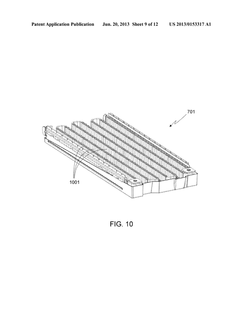
[0009] The present invention provides a vehicle battery pack integrated assembly, the assembly utilizing a battery pack enclosure that includes an enclosure top panel, an enclosure bottom panel, and a plurality of enclosure side members, where the battery pack enclosure is configured to hold a plurality of batteries, and where the battery pack is mounted between the passenger cabin floor panel and the driving surface. The system assembly includes a multi-layer thermal barrier interposed between the battery pack enclosure and the passenger cabin floor panel, where the multi-layer thermal barrier provides noise isolation, thermal isolation and vibration damping, where the multi-layer thermal barrier is compressed when the battery pack enclosure is mounted to the vehicle, and where the multi-layer thermal barrier is comprised of a first layer formed from a compressible and conformable elastic material and a second layer formed from a conformable thermally insulating material. A waterproof seal may be interposed between the battery pack enclosure and the vehicle, thus sealing the multi-layer thermal barrier between the battery pack enclosure and the passenger cabin floor. The multi-layer thermal barrier may also include a moisture barrier layer that encases the first and second layers, for example a moisture barrier layer fabricated from a plastic such as a low-density polyethylene (LDPE) thermoplastic. A sealant may be used to seal and bond the moisture barrier layer to the battery pack enclosure. [0010] In another aspect of the invention, the multi-layer thermal barrier may have an acoustic insertion loss of greater than 10 dB for frequencies between 1000 Hz and 10 kHz; alternately, the multi-layer thermal barrier may have an acoustic insertion loss of greater than 20 dB for frequencies between 1000 Hz and 10 kHz. [0011] In another aspect of the invention, the multi-layer thermal barrier may have a damping loss factor of at least 0.1; alternately, the multi-layer thermal barrier may have a damping loss factor of at least 0.3. [0012] In another aspect of the invention, the second layer of the multi-layer thermal barrier may have a thermal conductivity of less than 0.25 W/m-K at a temperature of 1000 degrees C.; alternately, the second layer of the multi-layer thermal barrier may have a thermal conductivity of less than 0.15 W/m-K at a temperature of 1000 degrees C.; alternately, the second layer of the multi-layer thermal barrier may have a thermal conductivity of less than 0.1 W/m-K at a temperature of 1000 degrees C. [0013] In another aspect of the invention, the second layer of the multi-layer thermal barrier may be capable of withstanding temperatures of more than 1000 degrees C. continuously; alternately, the second layer of the multi-layer thermal barrier may be capable of withstanding temperatures of more than 1000 degrees C. for a period of at least 10 seconds. [0014] In another aspect of the invention, the first and/or second layer of the multi-layer thermal barrier may have a compression modulus of at least 1.5 PSI at 25% compression. [0015] In another aspect of the invention, the first layer of the multi-layer thermal barrier may be comprised of a closed cell foam material such as a closed cell foam consisting of polyurethane, polyethylene, or ethylene propylene diene monomer (EPDM) foam. [0016] In another aspect of the invention, the second layer of the multi-layer thermal barrier may be comprised of silica/calcium oxide fibers, silica/calcium oxide/magnesium oxide fibers, a basalt fiber based needled pad, silica/silica fibers, alumina, Kevlar or Nomex. [0017] A further understanding of the nature and advantages of the present invention may be realized by reference to the remaining portions of the specification and the drawings.

